

Through years of working with testing equipment we have manufactured the ideal equipment for your needs! Please contact us to enquire about what equipment you need as not all of the equipment we can provide is reflected here!
Use the button below or email salesvd@vitaldrive.net to get in touch with our test equipment specialist that will guide you through our products!

High Voltage Inc. - PTS Series
The PTS Series combine high voltage DC hipots and HV megohmmeter instruments, offering two important tests within one unit. Users can perform high voltage DC hipot/proof and current leakage testing as well as resistance measurement testing. Most HVI models offer a higher output current than competitors’ products for quicker charging of capacitive loads like cables. Like all of our portable test equipment, the PTS Series is designed to withstand the rigors of field use.

HIGH VOLTAGE INC. - VLF SERIES
VLF hipots perform voltage withstand tests and provide the voltage source for diagnostic cable testing. There is no better method for verifying the AC integrity of a cable than applying VLF AC voltage. Tan delta and partial discharge measurement accessories are frequently purchased along with VLF equipment to extend their capabilities.

Portal combined device CTS-1006
Portable combined device for testing and defining fault location of cable sheath CTS-1006 is intended for the following works:
testing of cable sheath with XLPE insulation, equipped with the function of leakage current measuring;
burning of faulted sheath of cable with XLPE insulation;
fault location in sheath of cable with XLPE insulation using method of measuring difference of potential during surge voltage generator operating.

Surge Generator SG - 2000
A surge generator is used to inject a high voltage DC surge into the faulty cable. By supplying a sufficiently high voltage to the faulty cable, the open‐circuit fault will break down creating a high-current arc. This high current arc makes a characteristic thumping sound at the exact location of the fault.

Measuring bridge S-709
The bridge S-709 was intended for distance and fault locating in power cable lines with the help of bridge methods (of Muller, Kupfmuller, Hillborn/Graf), and distance definition to the place of fault in the power cable sheath.

Inductive fault locator set IFL-1210
Inductive Fault Locator set is intended to determine location and laying depth of hidden communications (power and signal cables, pipelines) at a depth of up to 10 m and at a distance of up to 5 km from the generator connection point as well as to locate the cable lines defective places.
«IFL -1210» is intended to survey of areas before
construction works commencing.

CFL535F Cable Fault Locator
The CFL535F is an advanced instrument capable of identifying a wide range of cable faults. The instrument uses a technique called Pulse Echo (Also known as time Domain Reflectometry or TRT). A pulse is transmitted into a cable of a specific and will cause a proportion of the pulse to be reflected. These reflections are displayed as a trace on the instrument.
The CFL535F can be used on any cable consisting of at least two insulated metallic elements, one of which may be the armouring or screen of the cable.
Dual inputs and large graphic display allow a wide range of comparative test to be performed between cable pairs and/or stored results.
The instrument has 15 memories, enabling test results to be displayed and compared with live or real time results.
The download feature allows transfer of waveform data to and from a Computer, using the TraceMaster software, for analysis and storage for reference.
The display and controls of the CFL535F have been ergonomically arranged so that the instrument is easy to use.
The instrument controls consist of the following
L1 input channel 1
L2 input channel 2
Contrast:Display contrast adjustment allows the user to adjust the contrast of the LCD Display for optimum viewing comfort
Tx Null:Allows the user to reduce the amplitude of the transmitted pulse on the displayed trace, allowing reflections close to the start of the cable (normally referred to as the “Dead Zone” to be identified. Refer to the section on Tx Null for further details.

DET10C and DET20C Clamp on Ground Resistance Tester
The clamp-on ground resistance tester enables the user to measure the ground resistance of a ground rod without the use of auxiliary ground rods. The clamp-on ground resistance tester is used in multi-grounded systems without disconnecting the ground under test.

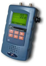
Digital Earth Leakage Clampmeter DCM300E
The DCM300E is a rugged lightweight pocket size clamp meter designed to measure a.c. earth leakage currents. This enables earth leakage faults to be detected and located without having to isolate and disconnect circuit wiring. Additionally, the DCM300E measures a.c. circuit currents up to 300 Amps.
Powered by two LR44 or SR44 cells, the instrument design takes full advantage of microprocessor technology and features a clear 3½ digit LCD combining digital and bargraph analogue readings.
The two position mode switch provides 4 ranges: 30 mA, 300 mA, 30 A and 300 A, with minimum resolution of 0,01 mA on the 30 mA range.
To conserve battery power, Auto shut off operates after a period of 10 minutes of inactivity by the instrument. The instrument can be switched back on by selecting Off and On again.
0,01 mA resolution
EMC & IEC1010 compliance
30 mA, 300 mA, 30 A & 300 A ranges
Pocket sized & lightweight
40 mm jaw size
Analogue Bargraph Display

Fluke 43B Power Quality Analyzer
Circuit breakers that trip, transformers that overheat, motors that burn out, machines that don’t function properly; whatever the problem, you can quickly and easily identify the cause with the Fluke 43B Power Quality Analyzer.
As a Power Quality Analyzer it is optimized for industrial measurements on the 50 Hz fundamental frequency. Because its frequency range extends from 10 to 400 Hz, it’s also ideal for aviation, marine and railway applications.
Besides the unique extended frequency range, the Fluke 43B is the only instrument that combines the capabilities of a Power Quality Analyzer, a 20 MHz oscilloscope, a multimeter and data recorder in a single tool.

Micro-Ohmmeter 6250
The Model 6250 Micro-Ohmmeter is used to perform low resistance measurements from 0.1µΩ to 2500Ω. There are seven ranges with test currents from 1mA to 10 A.
The front end of the micro-ohmmeter employs a four-wire Kelvin configuration, which eliminates test lead resistance for a measurement accuracy of 0.05%. A built-in circuit filters out AC signals.
The Model 6250 Micro-Ohmmeter is packaged in a sealed field case well suited for shop and field use. Power is supplied by a long-life NiMH battery pack with a built-in recharger (220V).
The large, easy-to-read liquid crystal display is 2.25 x 4.00". It displays the value of resistance, metal type, reference and ambient temperatures (if selected), alarm conditions (if selected), test current and range and test mode (Resistive, Inductive or Auto).
For operator safety and instrument protection, the micro-ohmmeter is fuse protected at the inputs. Two fuses, accessible behind the front panel, protect against stored energy in inductive loads.
Enhanced internal circuitry protects against possible inductive kickback when the current is shut off.
A built-in thermal switch protects the micro-ohmmeter against overheating on the 10A range when in continuous use.

Model 380801-380803
Extech 380801 Power Analyzer Datalogger offers the following features:
Convenient front panel plug-in and testing
Four displays for Watts, PF/VA, V/KHZ, Amperes
True power, true RMS for AC Voltage (V) and Current(A)
Datalogger stores over 1000 readings (Model 380803)
Auto Range for Watts and Volts
RS-232 PC Interface
Windows Applications Software

Radar Engineers Model 1669
The Model 1669 is specifically designed for use in conjunction with impulse generators (“thumpers”) and energy separating filters in arc reflection systems. It captures and holds the waveform created when a thump causes a fault to arc to ground.
The Model 1669 Digital Storage Radar operates on the principle of pulse reflection to localize the source of power failures in shielded underground cable. This method of cable fault location is simple and fast.
The Model 1669 applies a low voltage pulse to the cable. The pulse travels down to the cable insulation until it encounters a change in electrical characteristics, such as that caused by a splice, short or open. At that point, a reflection of pulse energy occurs. The nature of the reflection depends on the type of change encountered.
The initial output pulse and any impedance caused reflections are shown on the display screen. When viewing the trace, the generated pulse is seen on the left of the screen. Everything to the right represents reflections of what the pulse encounters in the cable.
The distance to any reflection of fault along the trace is measured by moving the right marker to the point of interest. The distance of the fault is then shown on the display.

T5-1000 Tester –Volts/Ohms/Amps
Measure voltage, current and check continuity with one tool.
Measures up to 1000 V ac or dc
Measures up to 100.0 A
Measures resistance up to 1000 Ω
OpenJaw™ lets you measure current without breaking the circuit
Two year warranty
Detects 90-600 V
Safety sheet inside
One-year warranty1AC
Voltage Tester
Tip glows red when voltage present.
Portable PD recorder and diagnostic system xdp ii
The XDP II is a portable device for, online, factory and laboratory partial discharge measurement on electrical apparatus, or components. The XDP II can be used in accordance to IEC 60270. It records partial discharge measurements for computer analysis and diagnostic using the optional XDP II software for a PC. Using the appropriate accessories, the XDP II can be used in several applications.
The XDP II is an ultra-wide-band amplification system allowing to measure PD activity. It uses a very high speed detection technique to detect PD activities. The XDP II displays graphically PD wave form and the built-in speaker allows listening to PD activities. This information can be recorded in the XDPII along with date and time of the reading. The recorded measurements remain stored in memory even when the XDP II is shut off. This allows the transfer of these recordings to a computer upon return from the worksite.